FIELD NOTES
Real instruments.
Real problems.
A few lessons learned the hard way.
If you want to save a few site visits, protect your data, and make sure the number on screen actually deserves your trust, here are a few field lessons worth keeping.
Small checks, real fixes, and the kind of details that can save hours — sometimes days — of troubleshooting. Some lessons cost a manual. Others cost a weekend.

Choose an environment to explore what I learned from its instruments.
Water Quality
GENERAL FIELD PRACTICE — NOT MODEL-SPECIFIC
Your pH buffer has a temperature too.
WORTH KNOWING
Check the buffer temperature and the correct value before calibrating — and check whether your software compensates automatically.
WHY CARE? A calibration mistake can create a very convincing environmental problem that never happened.
Technical detail
GENERAL FIELD PRACTICE — NOT MODEL-SPECIFIC
- Buffer chemistry and sensor temperature compensation are separate questions. Use the table for the actual standard, not a generic copied value.
- Manual-entry and automatic-recognition workflows differ, even between software and handheld interfaces for the same sonde.
 In-Situ
Aqua TROLL 500
Shared Aqua TROLL sensor / integration guidance, not an 800-specific defect. Confirm the fitted sensor and current model manual.
DON’T PANIC YET
pH drifting or refusing calibration? Check the reference filling solution before blaming the sensor — or the water.
Technical detail
A · Manufacturer-documented guidance, not a claim of a model defect.
- WQ-INS-01: applies to the refillable 0063470 pH/ORP sensor shared across these sondes.
- Inspect filling solution, bubbles and junction condition; service by the sensor procedure, then recalibrate.
REALITY CHECK
pH 7 looking suspicious? Check the raw mV too. A pretty calibration screen doesn’t automatically mean a healthy electrode.
Technical detail
A · Manufacturer-documented guidance, not a claim of a model defect.
- WQ-INS-01/02: raw mV, slope and offset support diagnosis of the shared pH sensor.
- Compare with the current sensor/model limits. AT500 numeric windows are not asserted here for every model.
HIDDEN TROUBLEMAKER
A perfect-looking 0.0 may actually mean “no valid reading.” Check the Data Quality ID before putting that zero in a report.
Technical detail
A · Manufacturer-documented guidance, not a claim of a model defect.
- WQ-INS-10: the documented Modbus parameter block includes a quality ID and a configurable offline sentinel, default 0.0.
- This is an integration behaviour, not a reported model defect. Not every zero is invalid; SDI-12 does not expose the same block.
+ One more from the field
ONE MORE FROM THE FIELD
“RDO Cap expired” isn’t the sonde announcing its death. The cap reached its service life — replace it, calibrate, continue.
Technical detail
A · Manufacturer-documented guidance, not a claim of a model defect.
- WQ-INS-04: cap expiry and replacement apply to the fitted RDO cap generation.
- Service lives differ between cap types. Follow that cap’s instructions; do not apply one lifetime to all Aqua TROLL models.
Why it matters: A believable number without its quality status can be more dangerous than no number.
Aqua TROLL 600
Shared Aqua TROLL sensor / integration guidance, not an 800-specific defect. Confirm the fitted sensor and current model manual.
DON’T PANIC YET
pH drifting or refusing calibration? Check the reference filling solution before blaming the sensor — or the water.
Technical detail
A · Manufacturer-documented guidance, not a claim of a model defect.
- WQ-INS-01: applies to the refillable 0063470 pH/ORP sensor shared across these sondes.
- Inspect filling solution, bubbles and junction condition; service by the sensor procedure, then recalibrate.
REALITY CHECK
pH 7 looking suspicious? Check the raw mV too. A pretty calibration screen doesn’t automatically mean a healthy electrode.
Technical detail
A · Manufacturer-documented guidance, not a claim of a model defect.
- WQ-INS-01/02: raw mV, slope and offset support diagnosis of the shared pH sensor.
- Compare with the current sensor/model limits. AT500 numeric windows are not asserted here for every model.
HIDDEN TROUBLEMAKER
A perfect-looking 0.0 may actually mean “no valid reading.” Check the Data Quality ID before putting that zero in a report.
Technical detail
A · Manufacturer-documented guidance, not a claim of a model defect.
- WQ-INS-10: the documented Modbus parameter block includes a quality ID and a configurable offline sentinel, default 0.0.
- This is an integration behaviour, not a reported model defect. Not every zero is invalid; SDI-12 does not expose the same block.
+ One more from the field
ONE MORE FROM THE FIELD
“RDO Cap expired” isn’t the sonde announcing its death. The cap reached its service life — replace it, calibrate, continue.
Technical detail
A · Manufacturer-documented guidance, not a claim of a model defect.
- WQ-INS-04: cap expiry and replacement apply to the fitted RDO cap generation.
- Service lives differ between cap types. Follow that cap’s instructions; do not apply one lifetime to all Aqua TROLL models.
Why it matters: A believable number without its quality status can be more dangerous than no number.
Aqua TROLL 800
Shared Aqua TROLL sensor / integration guidance, not an 800-specific defect. Confirm the fitted sensor and current model manual.
DON’T PANIC YET
pH drifting or refusing calibration? Check the reference filling solution before blaming the sensor — or the water.
Technical detail
A · Manufacturer-documented guidance, not a claim of a model defect.
- WQ-INS-01: applies to the refillable 0063470 pH/ORP sensor shared across these sondes.
- Inspect filling solution, bubbles and junction condition; service by the sensor procedure, then recalibrate.
REALITY CHECK
pH 7 looking suspicious? Check the raw mV too. A pretty calibration screen doesn’t automatically mean a healthy electrode.
Technical detail
A · Manufacturer-documented guidance, not a claim of a model defect.
- WQ-INS-01/02: raw mV, slope and offset support diagnosis of the shared pH sensor.
- Compare with the current sensor/model limits. AT500 numeric windows are not asserted here for every model.
HIDDEN TROUBLEMAKER
A perfect-looking 0.0 may actually mean “no valid reading.” Check the Data Quality ID before putting that zero in a report.
Technical detail
A · Manufacturer-documented guidance, not a claim of a model defect.
- WQ-INS-10: the documented Modbus parameter block includes a quality ID and a configurable offline sentinel, default 0.0.
- This is an integration behaviour, not a reported model defect. Not every zero is invalid; SDI-12 does not expose the same block.
+ One more from the field
ONE MORE FROM THE FIELD
“RDO Cap expired” isn’t the sonde announcing its death. The cap reached its service life — replace it, calibrate, continue.
Technical detail
A · Manufacturer-documented guidance, not a claim of a model defect.
- WQ-INS-04: cap expiry and replacement apply to the fitted RDO cap generation.
- Service lives differ between cap types. Follow that cap’s instructions; do not apply one lifetime to all Aqua TROLL models.
Why it matters: A believable number without its quality status can be more dangerous than no number.
 YSI / Xylem
EXO2
Shared EXO sensor practice; the logger-mode note is specifically historical EXO2 / DCP Adapter integration.
DON’T PANIC YET
SmartQC turned yellow? Don’t order a new sensor yet. Clean it, check the pH bulb/reference condition, then try again.
Technical detail
A · Manufacturer-documented guidance, not a claim of a model defect.
- WQ-EXO-01: EXO pH SmartQC uses calibration gain and offset; yellow calls for checks before replacement.
- Use fresh clear buffers and inspect for damage. Do not attempt to refill a non-serviceable reference module.
REALITY CHECK
Your pH buffer has a temperature too. Use the correct value for the calibration temperature — and watch the slope, not just “PASS.”
Technical detail
A · Manufacturer-documented guidance, not a claim of a model defect.
- WQ-EXO-02: in KorEXO, equilibrate temperature and use the buffer label’s value at that temperature.
- EXO handheld USA/NIST recognition includes temperature compensation. Follow the interface-specific procedure; do not assume all EXO interfaces behave identically.
HIDDEN TROUBLEMAKER
EXO2 works by itself but ignores the logger? With a DCP Adapter, check internal logging mode before rewiring half the station.
Technical detail
B · Agency / integrator field evidence; scope and historical limits apply.
- WQ-EXO-08: 2017–18 integrator reports linked EXO2/DCP silence to internal-logging-only configuration and template setup.
- Current software may have mitigated this workflow trap. Check current DCP instructions; do not transfer adapter advice to EXO3 native SDI-12.
+ One more from the field
ONE MORE FROM THE FIELD
Bluetooth vanished underwater? Relax. Radio and water aren’t best friends. Bring the sonde up, then connect.
Technical detail
B · Agency / integrator field evidence; scope and historical limits apply.
- WQ-EXO-14: a USGS EXO evaluation documented submerged Bluetooth loss. This is a radio limitation, not a claimed EXO3 defect.
- Reconnect above water using the approved interface. Protect any non-waterproof adapter from immersion.
Why it matters: One setup option can look exactly like a hardware failure — and cost a completely unnecessary site visit.
EXO3
Shared EXO pH and optical DO sensor guidance; no EXO2-specific DCP claim.
DON’T PANIC YET
SmartQC turned yellow? Don’t order a new sensor yet. Clean it, check the pH bulb/reference condition, then try again.
Technical detail
A · Manufacturer-documented guidance, not a claim of a model defect.
- WQ-EXO-01: EXO pH SmartQC uses calibration gain and offset; yellow calls for checks before replacement.
- Use fresh clear buffers and inspect for damage. Do not attempt to refill a non-serviceable reference module.
REALITY CHECK
Your pH buffer has a temperature too. Use the correct value for the calibration temperature — and watch the slope, not just “PASS.”
Technical detail
A · Manufacturer-documented guidance, not a claim of a model defect.
- WQ-EXO-02: in KorEXO, equilibrate temperature and use the buffer label’s value at that temperature.
- EXO handheld USA/NIST recognition includes temperature compensation. Follow the interface-specific procedure; do not assume all EXO interfaces behave identically.
HIDDEN TROUBLEMAKER
New optical DO cap, old coefficients? Load the replacement cap’s own coefficients before trusting the next calibration.
Technical detail
A · Manufacturer-documented guidance, not a claim of a model defect.
- WQ-EXO-03: applies when the EXO optical DO sensor is fitted; replacement caps have their own calibration coefficients.
- Follow the current cap instructions and verify the entered values before calibration.
+ One more from the field
ONE MORE FROM THE FIELD
Bluetooth vanished underwater? Relax. Radio and water aren’t best friends. Bring the sonde up, then connect.
Technical detail
B · Agency / integrator field evidence; scope and historical limits apply.
- WQ-EXO-14: a USGS EXO evaluation documented submerged Bluetooth loss. This is a radio limitation, not a claimed EXO3 defect.
- Reconnect above water using the approved interface. Protect any non-waterproof adapter from immersion.
Why it matters: One setup option can look exactly like a hardware failure — and cost a completely unnecessary site visit.
 OTT HydroMet / Hydrolab
HL7
HL7 / HL-series guidance. Calibration procedure evidence is limited; consult current Operating Software Help.
DON’T PANIC YET
Calibration looks strange? Before touching offsets, make sure the standard, temperature and sensor condition are actually right.
Technical detail
A · Manufacturer-documented guidance, not a claim of a model defect.
- HL guidance directs users to sensor-specific calibration procedures; check standards, cleanliness and stabilisation first.
- This is a calibration check, not evidence of an HL7 defect. Follow the fitted sensor’s current procedure.
REALITY CHECK
Enter the temperature-corrected pH buffer value, then run Calibration Check. Let the instrument keep the history — memory beats memory.
Technical detail
A/B · Documented software features; older agency procedure is indicative only.
- WQ-HL7-06: manual entry is supported by an older agency HL4/DataSonde procedure, not a fully verified current HL7 software workflow.
- HL software documents calibration checks/history. Confirm current Help before entering values; automatic buffer compensation is not established here.
HIDDEN TROUBLEMAKER
Red pH buffer near optical sensors? Bad colour choice. Some dyed standards can stain optical surfaces — use the recommended clear solution.
Technical detail
A · Manufacturer-documented guidance, not a claim of a model defect.
- WQ-HL7-01: the HL sonde manual warns against leaving turbidity sensors or fluorometers in coloured pH buffer.
- Use the specified colourless solution. This warning applies to the documented optical sensors, not every sensor or dye.
Why it matters: Sometimes the calibration liquid can become part of the measurement problem.
DS5X
Legacy DS5X. Clark membrane advice and optical LDO diagnosis are separate; agency bench checks are configuration-specific.
DON’T PANIC YET
A # beside the value doesn’t mean the whole sonde is dead. It means the reading is out of range.
Technical detail
A · Manufacturer-documented guidance, not a claim of a model defect.
- WQ-DS5X-05: the Series 5 manual identifies # as data outside the sensor range.
- Check the parameter and range before deciding on repair. Other status symbols have different meanings.
REALITY CHECK
Changed a Clark DO membrane? Give it time. A fresh membrane can drift for hours before settling down.
Technical detail
A · Manufacturer-documented guidance, not a claim of a model defect.
- WQ-DS5X-07: the Clark membrane needs conditioning before calibration; follow the manual’s soaking procedure.
- This does not apply to optical LDO; use that sensor’s separate instructions.
HIDDEN TROUBLEMAKER
LDO sitting neatly at 0.00? Don’t admire the zero yet. Bench current checks can help tell you whether a board is actually sick.
Technical detail
B · Agency / integrator field evidence; scope and historical limits apply.
- WQ-DS5X-01/03: a manufacturer-trained agency programme documented current-draw diagnosis for DS5X fitted with turbidity and LDO.
- Qualified service only. These are not universal Hach/OTT limits; a zero alone does not prove board failure or rule out genuine low oxygen.
+ One more from the field
ONE MORE FROM THE FIELD
Perfect readings with the wrong time are still the wrong story. Don’t forget the clock battery.
Technical detail
A · Manufacturer-documented guidance, not a claim of a model defect.
- WQ-DS5X-04: legacy Series 5 clock-battery maintenance is separate from measurement calibration.
- Follow the service procedure and reset date/time afterward. Do not apply DS5X replacement instructions to HL7.
Why it matters: Legacy instruments sometimes tell you more with a multimeter than with a dashboard.
 Solinst Eureka
Trimeter
Manta / Trimeter manual guidance, only for fitted sensors. Power-pack controls differ between models.
DON’T PANIC YET
Turbidity went negative? The instrument isn’t discovering negative mud. Check the low calibration point.
Technical detail
A · Manufacturer-documented guidance, not a claim of a model defect.
- WQ-EUR-02: the family manual permits negative turbidity to expose low-point calibration problems.
- Check the standard and clear optical volume; recalibrate where indicated rather than clipping values to zero.
REALITY CHECK
SRF says the calibration is unhappy? Listen to it. “Accept anyway” may feel brave, but the Cal Log remembers.
Technical detail
A · Manufacturer-documented guidance, not a claim of a model defect.
- WQ-EUR-01: Sensor Response Factor compares raw sensor response with a typical response and is saved in CAL.LOG.
- Review standard value, cleanliness and stability before overriding a warning. Acceptance is not proof of sensor health.
HIDDEN TROUBLEMAKER
Calibrating DO with weather-app pressure? Careful. Weather reports usually give sea-level pressure; the sensor needs the correct local pressure.
Technical detail
A · Manufacturer-documented guidance, not a claim of a model defect.
- WQ-EUR-03: set local barometric pressure before DO calibration following the fitted sensor’s manual.
- Check whether a reported pressure is local or sea-level corrected; do not assume every weather source reports the same quantity.
+ One more from the field
ONE MORE FROM THE FIELD
Battery ON. Logging ON. LEDs checked. The cheapest data loss is the deployment that never actually started.
Technical detail
A · Manufacturer-documented guidance, not a claim of a model defect.
- WQ-EUR-05: verify power, logging activation and a saved record using the procedure for your exact configuration.
- The internal-battery-pack switch is specific to Manta+ 35/40 configurations. Do not assume Trimeter has that switch or the same LED sequence.
Why it matters: The instrument can be perfectly healthy and still record absolutely nothing.
Manta+ 35
Manta / Trimeter manual guidance, only for fitted sensors. Power-pack controls differ between models.
DON’T PANIC YET
Turbidity went negative? The instrument isn’t discovering negative mud. Check the low calibration point.
Technical detail
A · Manufacturer-documented guidance, not a claim of a model defect.
- WQ-EUR-02: the family manual permits negative turbidity to expose low-point calibration problems.
- Check the standard and clear optical volume; recalibrate where indicated rather than clipping values to zero.
REALITY CHECK
SRF says the calibration is unhappy? Listen to it. “Accept anyway” may feel brave, but the Cal Log remembers.
Technical detail
A · Manufacturer-documented guidance, not a claim of a model defect.
- WQ-EUR-01: Sensor Response Factor compares raw sensor response with a typical response and is saved in CAL.LOG.
- Review standard value, cleanliness and stability before overriding a warning. Acceptance is not proof of sensor health.
HIDDEN TROUBLEMAKER
Calibrating DO with weather-app pressure? Careful. Weather reports usually give sea-level pressure; the sensor needs the correct local pressure.
Technical detail
A · Manufacturer-documented guidance, not a claim of a model defect.
- WQ-EUR-03: set local barometric pressure before DO calibration following the fitted sensor’s manual.
- Check whether a reported pressure is local or sea-level corrected; do not assume every weather source reports the same quantity.
+ One more from the field
ONE MORE FROM THE FIELD
Battery ON. Logging ON. LEDs checked. The cheapest data loss is the deployment that never actually started.
Technical detail
A · Manufacturer-documented guidance, not a claim of a model defect.
- WQ-EUR-05: verify power, logging activation and a saved record using the procedure for your exact configuration.
- The internal-battery-pack switch is specific to Manta+ 35/40 configurations. Do not assume Trimeter has that switch or the same LED sequence.
Why it matters: The instrument can be perfectly healthy and still record absolutely nothing.
Currents / ADCP

 Nortek
Signature 500
Nortek Signature / Aquadopp family guidance. Available QC outputs and calibration methods differ by instrument and mode.
DON’T PANIC YET
Current direction looks impossible? Check the compass calibration before blaming the ocean.
Technical detail
A · Manufacturer guidance; follow the exact model / firmware procedure.
- Check heading and compass calibration before deployment with the intended rig; nearby metal, magnets and batteries can affect it.
- Follow the exact model’s procedure and verify calibration quality. Strong magnetic interference may require a mounting change, not another calibration.
REALITY CHECK
Nice velocity profile? Good. Now check correlation and amplitude — pretty data can still be bad data.
Technical detail
A · Manufacturer guidance; follow the exact model / firmware procedure.
- Review amplitude and, where the instrument/mode provides it, correlation across beams and cells. Not every Aquadopp mode exposes identical diagnostics.
- Compare with model-specific noise and QC guidance. Do not impose one correlation percentage or amplitude threshold on every ADCP.
HIDDEN TROUBLEMAKER
The surface and seabed can quietly “help” your ADCP measure the wrong thing. Watch the sidelobes.
Technical detail
E · GENERAL FIELD PRACTICE — NOT A MANUFACTURER-SPECIFIC DEFECT
- Boundary interference is a general ADCP principle, not a defect unique to this brand. Rejection depends on beam geometry, tilt and deployment.
- Inspect boundary echoes, tilt and cell position; exclude contaminated cells using the deployment-specific procedure, not a universal percentage.
Why it matters: Bad heading can make a whole current-direction story confidently wrong.
Signature 1000
Nortek Signature / Aquadopp family guidance. Available QC outputs and calibration methods differ by instrument and mode.
DON’T PANIC YET
Current direction looks impossible? Check the compass calibration before blaming the ocean.
Technical detail
A · Manufacturer guidance; follow the exact model / firmware procedure.
- Check heading and compass calibration before deployment with the intended rig; nearby metal, magnets and batteries can affect it.
- Follow the exact model’s procedure and verify calibration quality. Strong magnetic interference may require a mounting change, not another calibration.
REALITY CHECK
Nice velocity profile? Good. Now check correlation and amplitude — pretty data can still be bad data.
Technical detail
A · Manufacturer guidance; follow the exact model / firmware procedure.
- Review amplitude and, where the instrument/mode provides it, correlation across beams and cells. Not every Aquadopp mode exposes identical diagnostics.
- Compare with model-specific noise and QC guidance. Do not impose one correlation percentage or amplitude threshold on every ADCP.
HIDDEN TROUBLEMAKER
The surface and seabed can quietly “help” your ADCP measure the wrong thing. Watch the sidelobes.
Technical detail
E · GENERAL FIELD PRACTICE — NOT A MANUFACTURER-SPECIFIC DEFECT
- Boundary interference is a general ADCP principle, not a defect unique to this brand. Rejection depends on beam geometry, tilt and deployment.
- Inspect boundary echoes, tilt and cell position; exclude contaminated cells using the deployment-specific procedure, not a universal percentage.
Why it matters: Bad heading can make a whole current-direction story confidently wrong.
Aquadopp family
Nortek Signature / Aquadopp family guidance. Available QC outputs and calibration methods differ by instrument and mode.
DON’T PANIC YET
Current direction looks impossible? Check the compass calibration before blaming the ocean.
Technical detail
A · Manufacturer guidance; follow the exact model / firmware procedure.
- Check heading and compass calibration before deployment with the intended rig; nearby metal, magnets and batteries can affect it.
- Follow the exact model’s procedure and verify calibration quality. Strong magnetic interference may require a mounting change, not another calibration.
REALITY CHECK
Nice velocity profile? Good. Now check correlation and amplitude — pretty data can still be bad data.
Technical detail
A · Manufacturer guidance; follow the exact model / firmware procedure.
- Review amplitude and, where the instrument/mode provides it, correlation across beams and cells. Not every Aquadopp mode exposes identical diagnostics.
- Compare with model-specific noise and QC guidance. Do not impose one correlation percentage or amplitude threshold on every ADCP.
HIDDEN TROUBLEMAKER
The surface and seabed can quietly “help” your ADCP measure the wrong thing. Watch the sidelobes.
Technical detail
E · GENERAL FIELD PRACTICE — NOT A MANUFACTURER-SPECIFIC DEFECT
- Boundary interference is a general ADCP principle, not a defect unique to this brand. Rejection depends on beam geometry, tilt and deployment.
- Inspect boundary echoes, tilt and cell position; exclude contaminated cells using the deployment-specific procedure, not a universal percentage.
Why it matters: Bad heading can make a whole current-direction story confidently wrong.
 Teledyne Marine / RDI
1200 kHz
WorkHorse family / owner-confirmed 600 and 1200 kHz experience. Verify generation and deployment configuration before applying diagnostic limits.
DON’T PANIC YET
Data looks ugly? Check the first-cell echo amplitude before opening the toolbox.
Technical detail
A · Manufacturer guidance; follow the exact model / firmware procedure.
- FST-042 uses first-depth-cell echo amplitude across all beams as a diagnostic starting point.
- Use limits only when the technical note matches your WorkHorse generation and settings. Inspect blockage and geometry; abnormal amplitude alone does not prove hardware failure.
REALITY CHECK
More cells doesn’t always mean more useful data. Blanking, range and cell size still need to make sense.
Technical detail
A · Manufacturer guidance; follow the exact model / firmware procedure.
- Choose blanking distance, cell size and profiling range for the specific frequency, mode and site.
- Check usable range and QC, not just the number of configured cells. Do not transfer WorkHorse II settings blindly to earlier units.
HIDDEN TROUBLEMAKER
Near the surface or bottom, the ADCP can hear the boundary louder than the water.
Technical detail
E · GENERAL FIELD PRACTICE — NOT A MANUFACTURER-SPECIFIC DEFECT
- Boundary interference is a general ADCP principle, not a defect unique to this brand. Rejection depends on beam geometry, tilt and deployment.
- Review amplitude profiles and exclude affected cells with the correct geometry-dependent method.
Why it matters: One bad setup can make months of current data look much more trustworthy than it really is.
600 kHz
WorkHorse family / owner-confirmed 600 and 1200 kHz experience. Verify generation and deployment configuration before applying diagnostic limits.
DON’T PANIC YET
Data looks ugly? Check the first-cell echo amplitude before opening the toolbox.
Technical detail
A · Manufacturer guidance; follow the exact model / firmware procedure.
- FST-042 uses first-depth-cell echo amplitude across all beams as a diagnostic starting point.
- Use limits only when the technical note matches your WorkHorse generation and settings. Inspect blockage and geometry; abnormal amplitude alone does not prove hardware failure.
REALITY CHECK
More cells doesn’t always mean more useful data. Blanking, range and cell size still need to make sense.
Technical detail
A · Manufacturer guidance; follow the exact model / firmware procedure.
- Choose blanking distance, cell size and profiling range for the specific frequency, mode and site.
- Check usable range and QC, not just the number of configured cells. Do not transfer WorkHorse II settings blindly to earlier units.
HIDDEN TROUBLEMAKER
Near the surface or bottom, the ADCP can hear the boundary louder than the water.
Technical detail
E · GENERAL FIELD PRACTICE — NOT A MANUFACTURER-SPECIFIC DEFECT
- Boundary interference is a general ADCP principle, not a defect unique to this brand. Rejection depends on beam geometry, tilt and deployment.
- Review amplitude profiles and exclude affected cells with the correct geometry-dependent method.
Why it matters: One bad setup can make months of current data look much more trustworthy than it really is.
WorkHorse family
WorkHorse family / owner-confirmed 600 and 1200 kHz experience. Verify generation and deployment configuration before applying diagnostic limits.
DON’T PANIC YET
Data looks ugly? Check the first-cell echo amplitude before opening the toolbox.
Technical detail
A · Manufacturer guidance; follow the exact model / firmware procedure.
- FST-042 uses first-depth-cell echo amplitude across all beams as a diagnostic starting point.
- Use limits only when the technical note matches your WorkHorse generation and settings. Inspect blockage and geometry; abnormal amplitude alone does not prove hardware failure.
REALITY CHECK
More cells doesn’t always mean more useful data. Blanking, range and cell size still need to make sense.
Technical detail
A · Manufacturer guidance; follow the exact model / firmware procedure.
- Choose blanking distance, cell size and profiling range for the specific frequency, mode and site.
- Check usable range and QC, not just the number of configured cells. Do not transfer WorkHorse II settings blindly to earlier units.
HIDDEN TROUBLEMAKER
Near the surface or bottom, the ADCP can hear the boundary louder than the water.
Technical detail
E · GENERAL FIELD PRACTICE — NOT A MANUFACTURER-SPECIFIC DEFECT
- Boundary interference is a general ADCP principle, not a defect unique to this brand. Rejection depends on beam geometry, tilt and deployment.
- Review amplitude profiles and exclude affected cells with the correct geometry-dependent method.
Why it matters: One bad setup can make months of current data look much more trustworthy than it really is.
 SonTek
Current-measurement instruments — exact model unconfirmed
GENERAL ADCP FIELD PRACTICE — NOT SONTEK-SPECIFIC DEFECT. Exact owner model is unconfirmed.
DON’T PANIC YET
Weird current near a boundary? Check the deployment geometry before blaming the river or sea.
Technical detail
E · GENERAL FIELD PRACTICE — NOT A MANUFACTURER-SPECIFIC DEFECT
- Boundary interference is a general ADCP principle, not a defect unique to this brand. Rejection depends on beam geometry, tilt and deployment.
- Check beam clearance, orientation and measurement volume against the site. No SonTek-specific limit is asserted.
REALITY CHECK
Depth, orientation and sampling settings are part of the measurement — not just setup paperwork.
Technical detail
E · GENERAL FIELD PRACTICE — NOT A MANUFACTURER-SPECIFIC DEFECT
- Record installation depth, orientation and sampling configuration so the measurements can be interpreted.
- Use the actual instrument manual for supported modes and coordinate systems; the exact SonTek model is not established here.
HIDDEN TROUBLEMAKER
A good instrument in the wrong place can still answer the wrong question.
Technical detail
E · GENERAL FIELD PRACTICE — NOT A MANUFACTURER-SPECIFIC DEFECT
- Choose a representative measurement location and check nearby structures and boundary effects.
- This is deployment practice, not evidence of a SonTek fault.
Why it matters: Good hardware cannot rescue a bad deployment.
Single-point current profiler experience
Generic family — manufacturer not confirmed
GENERAL CURRENT-MEASUREMENT PRACTICE
DON’T PANIC YET
Current looks strange? Check depth, orientation and mounting before blaming the water.
REALITY CHECK
One point measures one point. Don't accidentally turn it into a full water-column story.
HIDDEN TROUBLEMAKER
A shifted mount or fouled sensor can slowly change the reading without ever looking “offline.”
Why it matters: A good current reading can still be the wrong answer if it comes from the wrong place.
Weather
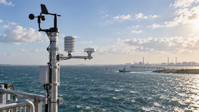
 Lufft / OTT HydroMet
Weather instruments — exact model unconfirmed
GENERAL ULTRASONIC WEATHER-SENSOR PRACTICE — only where ultrasonic wind sensing is fitted; not a Lufft-specific defect.
DON’T PANIC YET
Coastal wind suddenly looks strange? Check the sensor face before checking the forecast.
Technical detail
E · GENERAL FIELD PRACTICE — NOT A MANUFACTURER-SPECIFIC DEFECT
- Inspect the exposed acoustic path for contamination or obstruction using the instrument’s permitted inspection procedure.
- This is general practice from the supplied dossier, not manufacturer-confirmed Lufft salt-failure evidence.
REALITY CHECK
Installation and exposure matter as much as the sensor itself.
Technical detail
E · GENERAL FIELD PRACTICE — NOT A MANUFACTURER-SPECIFIC DEFECT
- Check mounting, orientation and nearby obstacles against the intended measurement site.
- Use the actual model manual for cleaning and mounting; no Lufft-specific clearance is prescribed here.
HIDDEN TROUBLEMAKER
Salt, obstruction and orientation can quietly make good hardware produce bad weather data.
Technical detail
E · GENERAL FIELD PRACTICE — NOT A MANUFACTURER-SPECIFIC DEFECT
- Separate environmental exposure from hardware diagnosis; compare with a suitable reference after approved maintenance.
- No universal salt-failure mechanism or cleaning chemical is claimed for Lufft.
Why it matters: A clean-looking station can still be measuring a dirty environment.
 Gill Instruments
MaxiMet GMX family
MaxiMet GMX models with the relevant wind / compass sensors fitted; siting guidance, not a product-defect claim.
DON’T PANIC YET
Wind low from one direction? Check whether the mast is standing in the way.
Technical detail
A · Manufacturer guidance; follow the exact model / firmware procedure.
- The MaxiMet manual recommends mounting the boom on the prevailing-wind side with clear airflow.
- Inspect mast and nearby obstructions against the affected wind direction before questioning the sensor.
REALITY CHECK
Compass looks strange? Keep ferrous objects away. The sensor is measuring weather, not your steelwork.
Technical detail
A · Manufacturer guidance; follow the exact model / firmware procedure.
- Where a compass is fitted, follow the model’s clearance requirements for ferrous material and verify orientation.
- Check mounting level and nearby interference; do not assume every GMX model includes a compass.
HIDDEN TROUBLEMAKER
Perfect sensor, bad siting = perfectly biased weather.
Technical detail
A · Manufacturer guidance; follow the exact model / firmware procedure.
- Review airflow, orientation and local exposure as part of commissioning and subsequent site changes.
- Siting bias is not proof of a Gill defect. Compare against a suitable independent reference.
Why it matters: A mast shadow can quietly bias every wind-dependent decision.
 R. M. Young
Weather instruments — exact model unconfirmed
GENERAL FIELD PRACTICE — mechanical wind sensors only; owner’s exact R. M. Young model is unconfirmed.
DON’T PANIC YET
Wind direction stuck? Make sure the vane can actually move before opening the software.
Technical detail
E · GENERAL FIELD PRACTICE — NOT A MANUFACTURER-SPECIFIC DEFECT
- Where a mechanical vane is fitted, inspect for obstruction and freedom of movement using the safe service procedure.
- Do not apply vane or bearing advice to ultrasonic sensors. No specific Young fault is established.
REALITY CHECK
Mechanical wind sensors still need mechanical attention. Bearings are part of the measurement.
Technical detail
E · GENERAL FIELD PRACTICE — NOT A MANUFACTURER-SPECIFIC DEFECT
- Check mechanical condition under the exact sensor’s maintenance schedule.
- Do not invent a replacement interval or lubricant; follow manufacturer service instructions.
HIDDEN TROUBLEMAKER
A constant direction offset often smells more like orientation than meteorology.
Technical detail
E · GENERAL FIELD PRACTICE — NOT A MANUFACTURER-SPECIFIC DEFECT
- Verify alignment, north reference and any configured offset against an independent direction reference.
- An offset is a diagnostic clue, not proof of a mechanical or manufacturer defect.
Why it matters: A small mechanical problem can quietly become a big data problem.
Tide / Water Level

E · GENERAL FIELD PRACTICE — NOT A MANUFACTURER-SPECIFIC DEFECT
Weather can look like tide.
WORTH KNOWING
Using a non-vented pressure sensor? Atmospheric pressure is inside the measurement too — compensate it before calling every weather front a tide event.
WHY CARE? Weather can appear as water-level change if the pressure measurement is not compensated correctly.
Technical detail
E · GENERAL FIELD PRACTICE — NOT A MANUFACTURER-SPECIFIC DEFECT
- Non-vented absolute sensors measure water plus atmospheric pressure. Apply appropriate, time-aligned barometric compensation.
- Vented sensors reference the atmosphere through a vent path: keep it clear and dry. Do not apply absolute-sensor compensation a second time.
 Obscape
Level Gauge / Tide / PTM family
GENERAL FIELD PRACTICE — radar / water-level installation; not an Obscape model-specific fault.
DON’T PANIC YET
Radar level disappeared? Check whether something is physically sitting in the measurement path.
Technical detail
E · GENERAL FIELD PRACTICE — NOT A MANUFACTURER-SPECIFIC DEFECT
- For radar configurations, inspect the measurement path and mounting for obstruction using safe access.
- This does not describe submerged pressure sensors; diagnose their measurement path separately.
REALITY CHECK
Water level only means something when the reference level is right.
Technical detail
E · GENERAL FIELD PRACTICE — NOT A MANUFACTURER-SPECIFIC DEFECT
- Check the survey datum, sensor reference point and conversion from measured distance to level.
- Record offsets and compare with an independent reference; do not change offsets to hide an unexplained mismatch.
HIDDEN TROUBLEMAKER
A clean radar sensor with a bad reference can still give you very precise nonsense.
Technical detail
E · GENERAL FIELD PRACTICE — NOT A MANUFACTURER-SPECIFIC DEFECT
- Repeatability does not establish datum accuracy. Recheck reference marks after mounting movement.
- General installation practice only; no Obscape failure rate or model defect is claimed.
Why it matters: Precise numbers do not rescue a bad datum.
 Campbell Scientific
Tide / water-level monitoring systems — exact sensor unconfirmed
SYSTEM-LEVEL FIELD PRACTICE / OWNER EXPERIENCE — Campbell-based monitoring systems, not a dedicated Campbell tide-gauge model.
DON’T PANIC YET
Water level wrong? Check the raw sensor value and offset before blaming the tide.
Technical detail
E · GENERAL FIELD PRACTICE / OWNER EXPERIENCE — NOT MANUFACTURER-CONFIRMED
- Trace raw input through units, multiplier and offset to the reported level.
- Use the actual sensor/logger configuration; no exact tide sensor model is established here.
REALITY CHECK
Datum first. Scaling second. Dashboard last.
Technical detail
E · GENERAL FIELD PRACTICE / OWNER EXPERIENCE — NOT MANUFACTURER-CONFIRMED
- Confirm reference level and units before checking display formatting.
- Compare raw and scaled records with an independent reference; retain the calibration history.
HIDDEN TROUBLEMAKER
Correct level with the wrong timestamp is still the wrong tide.
Technical detail
E · GENERAL FIELD PRACTICE / OWNER EXPERIENCE — NOT MANUFACTURER-CONFIRMED
- Check logger time, timezone and measurement versus reporting timestamps.
- Verify alignment across the acquisition and display chain, especially after a power interruption.
Why it matters: Tide data needs both the right level and the right time.
 Valeport / Teledyne Valeport
TideMaster
TideMaster pressure-transducer configuration. Site Cal and pressure-drift guidance must not be applied to radar without its own procedure.
DON’T PANIC YET
Tide slowly drifting away from reality? Run a Cal Check before blaming the sea.
Technical detail
A · Manufacturer guidance; follow the exact model / firmware procedure.
- Compare against an independent level reference tied to the same datum before adjusting anything.
- Use the pressure-transducer Cal Check procedure; an unexplained mismatch alone is not a reason to recalibrate.
REALITY CHECK
Adjusted the calibration? Good. Now verify it. “I changed it” and “it’s correct” are not the same sentence.
Technical detail
A · Manufacturer guidance; follow the exact model / firmware procedure.
- Site Cal calculates gain and offset from suitable reference measurements. Follow the fixed- or moving-transducer procedure.
- Run Cal Check after adjustment and compare with the current independent reference level.
HIDDEN TROUBLEMAKER
Pressure-based level can drift slowly enough that nobody notices until the reference disagrees.
Technical detail
E · GENERAL FIELD PRACTICE — NOT A MANUFACTURER-SPECIFIC DEFECT
- Pressure drift is a general sensor principle, not a unique TideMaster defect.
- Schedule independent checks and inspect datum, mounting and environmental effects before assigning a cause.
Why it matters: A small level bias can affect navigation, dredging and environmental interpretation.
Telemetry
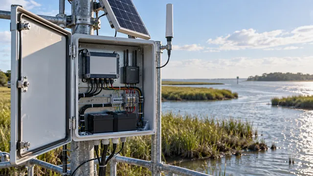
 Moxa
Moxa
OnCell family
OnCell family — general cellular checks supported by Moxa guidance; ports, antenna counts and commands depend on the exact unit.
DON’T PANIC YET
Modem says connected but the server is lonely? Check the APN first.
Technical detail
A · Manufacturer guidance; follow the exact model / firmware procedure.
- Compare APN and account settings with the SIM provider’s approved configuration.
- Network registration does not prove routing or delivery; verify a record at its destination.
Moxa · Cellular connection troubleshooting
Source temporarily unavailable at the release link check. Citation retained from the supplied research dossier.
REALITY CHECK
Test the SIM somewhere known-good before accusing the modem.
Technical detail
A · Manufacturer guidance; follow the exact model / firmware procedure.
- Check activation and SIM PIN/PUK status. Use the account’s APN in a compatible known-good device.
- Do not guess unlock codes. A successful SIM test narrows the fault; it does not certify the original modem’s routing or antenna system.
Moxa · Cellular connection troubleshooting
Source temporarily unavailable at the release link check. Citation retained from the supplied research dossier.
HIDDEN TROUBLEMAKER
LTE antenna in the GPS port? Everything can look beautifully connected to absolutely nothing.
Technical detail
A · Manufacturer guidance; follow the exact model / firmware procedure.
- Where separate LTE/GNSS ports exist, verify their labels and the correct antenna type.
- Use the exact unit’s antenna requirements. Moxa Connection Manager examples do not establish a universal OnCell port layout or antenna count.
Moxa · Cellular connection troubleshooting
Source temporarily unavailable at the release link check. Citation retained from the supplied research dossier.
Why it matters: “Connected” and “delivering data” are two different achievements.
 Teltonika Networks
RUT family
RUT family; distributor setup guidance. Menus and supported network features vary by model and firmware.
DON’T PANIC YET
Router connected but no internet? Auto APN may have guessed wrong.
Technical detail
B · Distributor-documented setup guidance; not a product-defect claim.
- Compare Auto APN’s selected profile with the SIM supplier’s APN; enter an approved custom value where required.
- Follow the exact firmware interface. A private APN may intentionally restrict public internet access.
REALITY CHECK
Signal bars look happy? Nice. Now check whether traffic is actually moving.
Technical detail
E · GENERAL FIELD PRACTICE — NOT A MANUFACTURER-SPECIFIC DEFECT
- Inspect link status and available traffic counters, then verify delivery to the intended monitoring endpoint.
- Signal strength alone does not establish end-to-end access or correct routing.
HIDDEN TROUBLEMAKER
Private APN, VPN and routing can leave a healthy modem connected to nowhere useful.
Technical detail
E · GENERAL FIELD PRACTICE — NOT A MANUFACTURER-SPECIFIC DEFECT
- Check the authorised network path, VPN requirements and routes for the SIM account.
- Do not assume all private-IP SIMs require the same VPN, or weaken firewall controls to make a connection work.
Why it matters: Full signal strength does not prove the monitoring network is reachable.
Campbell Scientific
CELL215
Campbell CELL215 / CELL200-series setup. Carrier retirement is a network-compatibility check, not a claim that CELL215 is a 3G-only device.
DON’T PANIC YET
CELL215 won’t connect? Check the SIM seating and power before blaming the network.
Technical detail
A · Manufacturer guidance; follow the exact model / firmware procedure.
- Follow the manual for safe SIM insertion and seating; check power at both module and logger.
- Use the specified supply and check stability under load, rather than assuming an illuminated indicator proves adequate power.
REALITY CHECK
Test the SIM in a known-good device. One quick check can separate account trouble from hardware trouble.
Technical detail
A · Manufacturer guidance; follow the exact model / firmware procedure.
- Use a compatible known-good module with the account’s approved APN.
- A successful test supports account connectivity; still check the original module’s bands, configuration and installation.
HIDDEN TROUBLEMAKER
Old cellular technology can retire before the station does.
Technical detail
E · GENERAL FIELD PRACTICE — NOT A MANUFACTURER-SPECIFIC DEFECT
- CELL215 supports 4G LTE CAT-1 with older-network fallback. Check local carrier bands and service support; no current shutdown date is asserted.
- Retirement matters when a deployment depends on the affected technology. It does not automatically disable a compatible working LTE connection.
Why it matters: One network change can quietly take an entire monitoring fleet offline.
Loggers & Control
Campbell Scientific
CR series
CAMPBELL SCIENTIFIC — CR SERIES · shared notes with model-specific applicability; not universal faults.
DON’T PANIC YET
Applies to: CR series · where supported by the model’s CRBasic architecture
Missing records? Check SkippedScan before starting a fight with the modem.
Technical detail
A · Manufacturer guidance; follow the exact model / firmware procedure.
- Compare the SkippedScan counter with the missing-record times; skipped measurements and failed transmission are different failures.
- Pipeline buffer overflow matters only where PipelineMode is supported. CR300-series loggers run sequentially; do not prescribe PipelineMode to them.
- Review scan interval and processing load with MeasureTime, ProcessTime, MaxProcTime and MaxBuffDepth only where exposed by that model and compile mode.
HIDDEN TROUBLEMAKER
Applies to: CR1000X / CR300 / CR310 / CR350 · supported SDI-12 ports only
Two SDI-12 sensors sharing one address? Congratulations — now both think you’re talking to them.
Technical detail
A · Manufacturer guidance; follow the exact model / firmware procedure.
- Every sensor sharing an SDI-12 data bus needs a unique address. Verify responses individually using the documented transparent mode.
- Check power, wiring and port conflicts against the exact logger manual. CR1000X companion-port restrictions are not a universal pin map.
REALITY CHECK
Applies to: CR1000 / CR1000X · tables configured as ring memory
Your logger has a memory too. When ring memory fills, the oldest history quietly makes room for the newest.
Technical detail
A · Manufacturer-documented guidance, not a claim of a model defect.
- Collect records before the configured ring overwrites them. Check table fill times and whether FillStop is used instead.
- This note is scoped to CR1000/CR1000X ring-table behaviour. It does not equate CR300-series flash storage or power-loss retention with those models.
HIDDEN TROUBLEMAKER
Applies to: CR1000 / CR1000X: voltage diagnostic · CR300 / CR310: no equivalent readout · CR350: verify its manual
Tiny battery. Very large headache. Before a planned power shutdown, remember the backup clock battery.
Technical detail
A · Manufacturer guidance; follow the exact model / firmware procedure.
- Check backup-battery service guidance and clock continuity. CR1000/CR1000X can report LithiumBattery; CR300/CR310 do not report that voltage.
- Do not equate clock loss with loss of all records: CR300 flash data survive power removal. Confirm CR350 behaviour in its own manual; no universal voltage threshold or replacement instruction is prescribed.
+ One more from the field
ONE MORE FROM THE FIELD
Applies to: CR1000X · supported RS-485 ports only
Nothing talking? Check A/B before rewriting the code. Different manufacturers do not always label RS-485 the same way.
Technical detail
E · GENERAL FIELD PRACTICE — NOT A MANUFACTURER-SPECIFIC DEFECT
- Verify signal polarity and the exact port’s RS-485 support against both manuals; CR1000X port instructions are not universal.
- If the manuals indicate reversed A/B conventions, test the corrected pairing under the safe wiring procedure. Never interchange power and signal terminals.
Why it matters: “Station online” does not mean “complete, correctly timed data.”
CR200 / CR200X
GENERAL CAMPBELL / LEGACY LOGGER PRACTICE
DON’T PANIC YET
Sensor stopped talking? Check power, wiring, address and the raw input before blaming the logger.
REALITY CHECK
Simple logger doesn't mean simple problem. Scan timing, scaling and table setup can still quietly ruin the data.
HIDDEN TROUBLEMAKER
Legacy hardware loves one thing: assumptions. Check what the program actually stores, not what you think it stores.
Why it matters: Old hardware can still do good work — if the configuration is treated with respect.
OTT HydroMet
netDL 500 / 1000
OTT netDL 500 / 1000 — documented restart behaviour when data memory is nearly full.
DON’T PANIC YET
Logger slow after a power cut? Give it a minute before writing its obituary.
Technical detail
A · Manufacturer guidance; follow the exact model / firmware procedure.
- The operating instructions allow a delay of a few minutes before communication resumes after power restoration with nearly full memory.
- Check stable power and allow the documented recovery period; persistent failure requires further diagnosis.
REALITY CHECK
Check memory usage before replacing hardware. A nearly full logger has more work to do after restart.
Technical detail
A · Manufacturer guidance; follow the exact model / firmware procedure.
- Review data-memory utilisation and confirm records have reached the collection system.
- Collection is not proof that memory was cleared. Follow the retention procedure; back up records before any authorised deletion.
HIDDEN TROUBLEMAKER
A storage problem can dress up very convincingly as a communications problem.
Technical detail
A · Manufacturer guidance; follow the exact model / firmware procedure.
- The documented case is delayed communication after a power interruption with nearly full memory, not every communication failure.
- Correlate restart timing, power history and memory usage before replacing a modem or logger.
Why it matters: One memory issue can trigger an unnecessary site visit.
Obscape
PTM — Water Quality / ADCP / Weather / Tide / Camera
GENERAL FIELD PRACTICE / OWNER EXPERIENCE — separate PTM paths in the owner’s setup, not an Obscape fault claim.
DON’T PANIC YET
No data? Start with power, telemetry and the measurement path before calling the sensor dead.
Technical detail
E · GENERAL FIELD PRACTICE / OWNER EXPERIENCE — NOT MANUFACTURER-CONFIRMED
- Trace power, instrument output, PTM receipt and delivery separately.
- Owner/system practice only; public model-specific troubleshooting evidence is insufficient.
REALITY CHECK
Check what the PTM is actually receiving before judging what the cloud shows.
Technical detail
E · GENERAL FIELD PRACTICE / OWNER EXPERIENCE — NOT MANUFACTURER-CONFIRMED
- Compare available local records and timestamps with received records, using only supported diagnostic interfaces.
- Distinguish acquisition failure from delayed or failed delivery; do not assume a particular diagnostic screen exists.
HIDDEN TROUBLEMAKER
One PTM per instrument means separate failure paths. Check each one separately.
Technical detail
E · GENERAL FIELD PRACTICE / OWNER EXPERIENCE — NOT MANUFACTURER-CONFIRMED
- This describes the owner’s one-PTM-per-instrument arrangement, not every Obscape installation.
- Check power, connectivity and receipt for each path; one working device does not verify the others.
Why it matters: One healthy device does not clear the rest of the station.
RS-485 / Modbus — a two-wire naming problem
E · GENERAL FIELD PRACTICE — NOT A MANUFACTURER-SPECIFIC DEFECT
HIDDEN TROUBLEMAKER
Nothing talking? Check A/B before rewriting the code. Different manufacturers do not always label RS-485 the same way.
A two-wire naming problem can waste hours.
Technical detail
E · GENERAL FIELD PRACTICE — NOT A MANUFACTURER-SPECIFIC DEFECT
- Verify signal polarity and the exact port’s RS-485 support against both manuals; CR1000X port instructions are not universal.
- If the manuals indicate reversed A/B conventions, test the corrected pairing under the safe wiring procedure. Never interchange power and signal terminals.
Vibration
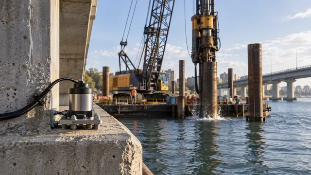
 Micromega Dynamics / RECOVIB
RECOVIB TREMOR
GENERAL VIBRATION-MONITORING PRACTICE — not RECOVIB defects. Gateway brand depends on the installation.
DON’T PANIC YET
Big vibration spike? Check what happened nearby — and make sure the monitor itself didn’t move — before calling it structural trouble.
REALITY CHECK
The sensor measures what reaches its mounting point. Bad coupling can make good hardware tell a bad story.
HIDDEN TROUBLEMAKER
Sensor healthy but nothing online? If access is permitted, check the gateway and SIM connection/configuration — including Teltonika where fitted.
Why it matters: A real vibration event and a bad installation can look surprisingly similar.
GPS / Positioning
 Garmin
Fixed / mobile / handheld GPS — exact models unconfirmed
GENERAL GNSS FIELD PRACTICE — exact Garmin model unconfirmed; not a product-defect claim.
DON’T PANIC YET
GPS dot wandering while you’re standing still? Give it some sky before blaming the map.
REALITY CHECK
Before sharing coordinates, check datum and coordinate format. Same place, very different-looking numbers.
HIDDEN TROUBLEMAKER
Buildings, steel and reflected signals can confuse positioning without making the receiver look broken.
Why it matters: Correct measurements attached to the wrong location are still the wrong record.
Teltonika
GNSS/GPS-capable telemetry units — exact models unconfirmed
GENERAL GNSS / INTEGRATION PRACTICE — exact model unconfirmed; not Teltonika product defects.
DON’T PANIC YET
Router online but GPS missing? Cellular connection and satellite fix are two separate friendships.
REALITY CHECK
Check fix quality and antenna view before trusting the coordinate.
HIDDEN TROUBLEMAKER
Metal protects electronics very well. Satellites are less impressed. Check where the GNSS antenna actually sits.
Why it matters: Connectivity proves communication — not position.
Underwater Noise
 Loggerhead Instruments
Snap Underwater Acoustic Recorder
Passive acoustics · underwater noise · WAV analysis
DON’T PANIC YET
Spectrogram suddenly looks dramatic? Listen before naming the event. Boats, rubbing debris and real underwater sound can all light up the screen.
REALITY CHECK
A loud-looking waveform is not automatically a loud ocean. Check sample rate, gain and hydrophone sensitivity before comparing sound levels.
HIDDEN TROUBLEMAKER
New SD card? Don't just drop it in and hope. FAT32 first — and check the formatting settings before the recorder goes underwater.
Technical detail
A · Manufacturer-documented guidance, not a claim of a model defect.
- The reviewed Snap manual requires FAT32 microSD storage; its Windows formatting workflow for cards larger than 32 GB specifies 64 KB cluster size.
- This instruction belongs to that Snap manual and workflow, not unrelated acoustic recorders. Confirm the correct card and back up data before formatting.
HEAR IT. SEE IT. THEN EXPLAIN IT.
Start with the WAV file, listen to the event, inspect the spectrogram, then separate environmental sound from vessels, handling or mechanical noise.
+ One more from the field
ONE MORE FROM THE FIELD
Still recording when you recover it? Stop the recording properly before touching the data. Five seconds now beats a storage headache later.
Technical detail
A · Manufacturer-documented guidance, not a claim of a model defect.
- For the reviewed Snap: hold UP + DN together to close the active recording file correctly. Then switch off and remove the microSD card.
- Follow the unit’s recovery instructions; do not interrupt an active file by removing the card.
Why it matters: A perfect underwater deployment can still become a useless dataset before analysis even starts.
Technical detail
A · Manufacturer-documented guidance, not a claim of a model defect.
- Snap saves WAV files, with configurable sample rate and software-adjustable gain. Check the settings used for each recording.
- The documented hydrophone is HTI-96-min. Use the sensitivity supplied for the actual unit, together with the recording gain and calibration chain.
- Visual waveform amplitude is not calibrated underwater sound pressure level. Listening and spectrogram review help interpret context; they do not establish acoustic thresholds, regulatory assessments or species identification.
Programming / Integration
CRBasic · Python · C / C++
E · OWNER FIELD EXPERIENCE · GENERAL FIELD PRACTICE — NOT MANUFACTURER-SPECIFIC
The sensor may be innocent.
HUSAM’S FIELD NOTE · GENERAL ELECTRONICS
Reading glued to the ceiling or floor? Before ordering another sensor, check the measurement electronics too.
Technical detail
E · OWNER FIELD EXPERIENCE · GENERAL FIELD PRACTICE — NOT MANUFACTURER-SPECIFIC
- A damaged analogue/input path can cause extreme readings even with a healthy sensor. This is owner experience/general electronics, not a manufacturer architecture or model-defect claim.
- Check the measurement chain. Board-level diagnosis requires qualified service personnel and the proper instrument/service procedure.
Manufacturer names and trademarks are shown only to identify equipment I have worked with. No manufacturer endorsement or affiliation is implied.